 USA / EN
 Middle East
 México / Espanol
Radiographic Testing of Welds
Radiographic testing of welds and weld testing are necessary steps in any pipeline construction process to detect flaws and defects within welded materials. One common method of non-destructive testing is radiographic testing, whereby radiographic images, or x-rays, of the weld are produced.
However, the actual production of these images represents a mere fraction of this process. The real work is done when the radiographer examines the negative images and interprets them. He or she must possess a sharp eye and keen sense of understanding as it relates to welding discontinuities and defects. This ability helps establish the weld’s internal integrity without destroying the welded joint.
A radiographer must identify typical welding defects when viewing and interpreting an image. [image credit: http://www.mocke.net/page.php?page=429 | Google image search]
A radiographer must identify typical welding defects when viewing and interpreting an image.
[image credit: http://www.mocke.net/page.php?page=429 | Google image search]
Welding Defects

Burn Through
This issue shows up on the image as a localized darker density area with fuzzy edges and is caused by a severe depression or crater-like hole at the bottom of the weld.
Cluster Porosity
This condition is caused by clusters of trapped gas and will appear on the image as rounded or slightly elongated clusters of dark spots.
Elongated Slag Inclusions (Wagon Tracks)
Caused when elongated cavities develop on both side of the root and contain slag or other foreign matter, these defects appear on the image as darker density lines with irregular width.
Excess Penetration
Caused by excess metal at the weld root, this condition will appear as a lighter density area at the center of the image and can be extended along the weld or isolated in circular drops.

External Undercut
A groove or channel in the surface of the plate along the weld edge causes this issue, and it will appear as an irregular dark density line that follows the edge of the image.
Internal Undercut
Caused by a groove in the main object stretched along the edge at the bottom or inner surface of the weld, this defect shows itself as an irregular dark density near the center of the image and along the edge of the root pass.
Scattered Porosity
When gas is trapped in cavities, this is the resulting defect, and it appears on the image as a dark and sharply defined shadow with rounded contours.
Slag Lines
Caused by elongated cavities containing slag or other low density foreign matter, these appear on the image as darker density lines that are irregular in width running parallel to the weld edge.
Transverse Cracks
Caused by metal fractures across the weld, these appear as fine dark lines running across the image.
Tungsten Inclusions
Caused by small pieces of tungsten trapped during the welding process, these defects manifest as random spots in the image that exhibit irregular lower densities.
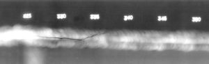
Longitudinal Cracks [image credit: sentinelltd.co.nz/Sentinel | Google Image Search]
Appearing on the image as dark lines along the length of the weld, these are caused by fractures.
Mismatch or Offset (Hi-Lo)
Caused by material pieces not being properly aligned prior to welding, this defect appears as an abrupt change in film density across the width of the weld image.
Weld Spatter
Caused by metal particles expelled during fusion welding, this appears on the image as white spots near the weld.

Lack of Fusion
Caused by elongated voids between the weld and base metals, this condition appears on the image as darker density lines, but unlike slag lines, these are straight and aligned lengthwise.
Lack of Penetration (LOP)
This condition results from either a lack of fusion in the weld root or a gap left by the failure of the weld metal to fill the root and can be identified on the image as continuous or intermittent dark lines in the center of the weld.